How to use Condor XC-002 Key Cutting Machine?
Matched product:
€1,175.00$1,245.50£1,020.96AUD1,946.15
- Item No. SL355
- Free Shipping
Condor XC-002 is the ideal key machine to start cutting laser (single, double, four-track etc.) and dimple keys (Cisa, Brisant, Mul-T-Lock etc.). Easy to use and extremely precise, you will cover a wide range of automotive and household keys.
How to use Condor XC-002 Key Cutting Machine?
1.INSTALLING MAIN HANDLE
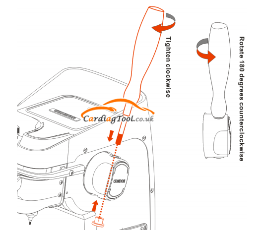
1) Insert the bottom of main handle into installing hole, which is by the right side of the machine body. Then cover the screw cap and rotate the handle clockwise until tightened.
2) If fully tightened, the main handle should be fix at a certain position and unable to move up or down.
3) If rotate the handle 180 degrees counterclockwise, the height of tracer and cutter can be changed freely.
2 INSTALLING SUB-HANDLE
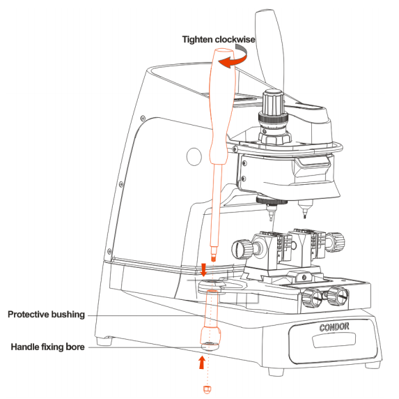
4) Insert the bottom of sub-handle into the installing hole, which is by the left side of the machine body. Put on the protective bushing and then plug in the lower bearing bore to avoid moving. Cover the screw cap and rotate the handle clockwise until tightened.
3.INSTALLING AND REMOVING PROBE/CUTTER
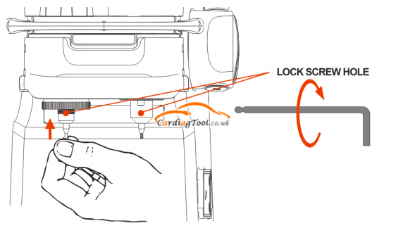
1) The left one is tracer and the right one is cutter. Put the tracer and cutter into the hole and to the top limit position. Then use 2.5mm Allen wrench to turn the lock screw clockwise respectively till the tracer and cutter are both tightened.
NOTE: When using 1.5mm cutter and 2.5mm cutter, tracer and cutter must select the top with the same diameter for processing.
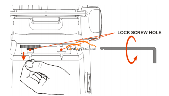
2) Insert the wrench into the hole, turn the lock screw counterclockwise, and then remove trace and cutter.
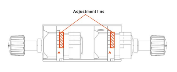
4. CLAMP INSTALLATION
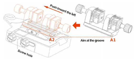
Aim the bump (A1: underneath the clamp) at the cutting bench’s groove (A2), push toward the left until A1 and A2 (shown above) are fully overlapped. Then use 4mm Allen wrench to tighten the screw
5. PROBE/CUTTER HEIGHT LEVEL ADJUSTMENT
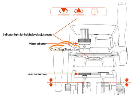
1) When the installation finished, push the main handle. If the tracer is higher than cutter, the indicator light on the left will turn on.
2) If the tracer is lower than cutter, the indicator light on the right will turn on.
3) According to the signal of indicator light, rotate the Micro-adjuster until tracer and cutter’s tops have both touched the clamp. In other words, they are at the same height. Then two indicator lights will on, adjustment finished.
NOTE:During the height level adjustment, main clamp and sub-clamp must at the same side.
6. ROTATION SPEED ADJUSTMENT
Rotation adjustment knob locates at the right side of the machine. There are two gears to control the rotating speed of motor.
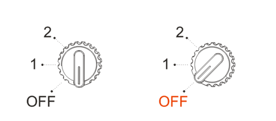
1) When the adjuster is at the neutral gear, motor stays at Turnoff mode; when it points to OFF, the light will be on, means the machine is ready to work.
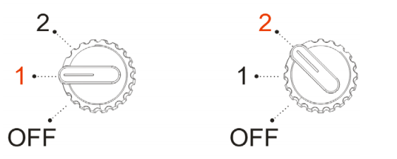
2) When the adjuster points to 1, the motor rotates at a low speed, about 6000rpm; when it points to 2, the rotation speed is higher, about 8000rpm.